
What's new in the Gallery?
Check This thread
Check This thread
Now … Voyager…
Moderators: tay666, Moderators
-
Splash-Art

- Seam Filler
- Posts: 319
- Joined: October 24th, 2012, 4:57 pm
- Location: Scottsdale, AZ
- Contact:
Re: Now … Voyager…
Dude, your work is beyond words! I appreciate all the pictures to showcase your talent, and to let us all see how you're piecing this beauty together. I can not wait to see the final pictures. Thank you!
-
Trekkriffic
- Jack of all Trades
- Posts: 697
- Joined: April 18th, 2014, 10:15 pm
Re: Now … Voyager…
Thanks! Comments like yours really make my day. I appreciate it! I figure another month or two and she’ll be done.Splash-Art wrote: ↑June 7th, 2023, 2:04 am Dude, your work is beyond words! I appreciate all the pictures to showcase your talent, and to let us all see how you're piecing this beauty together. I can not wait to see the final pictures. Thank you!
-
Trekkriffic
- Jack of all Trades
- Posts: 697
- Joined: April 18th, 2014, 10:15 pm
Re: Now … Voyager…
Fascinating video of me mixing paint...
Mixing up hull color “A” per the Revell instruction sheet. 70% light grey and 30% grey enamel:
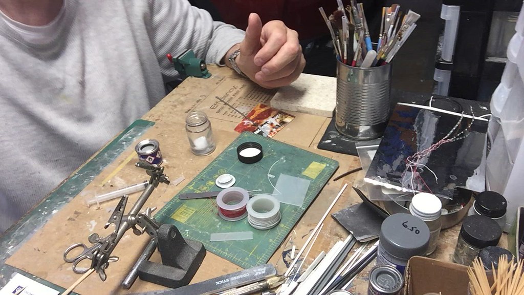
USS Voyager WIP Vid - 006 by Steve J, on Flickr
More pics...
Large secondary hull windows are masked off before painting the brass frames with Mister Surfacer thick primer:
USS Voyager WIP Img - 085 by Steve J, on Flickr
Large window groups unmasked after brushing with Mister Surfacer. The curved structural support beams on deck 2 are also given a brush:

USS Voyager WIP Img - 086 by Steve J, on Flickr
Recessed deck 2 egress hatch is painted with Mister Surfacer after modifications were complete:

USS Voyager WIP Img - 087 by Steve J, on Flickr
I found this sheet of .030 clear plastic sheet with its protective film still intact. I will use this to cut individual rectangular bits to fill in the smaller rectagular window openings in the hull. This will take some time to do but it should look great when I’m done:

USS Voyager WIP Img - 088 by Steve J, on Flickr
This is a sheet of extra decals meatloafr over on All Scale Trek printed for me when I was working on the Ent E. He included some sized to fit the Voyager too. Lots of good stuff to help with detailing a variety of kits:

USS Voyager WIP Img - 089 by Steve J, on Flickr
Secondary hull forward photorp launcher openings drilled out and filed to shape.
The openings will be filled with two tiny bits of clear styrene shown to the upper right:

USS Voyager WIP Img - 090 by Steve J, on Flickr
Spine photorp launchers opened up. Kit molded frames were sanded off and will be replaced with the thicker frames made from Evergreen strip shown to the right. Clear rectangular styrene bits will be inserted thru the new frames and out the back for lighting:

USS Voyager WIP Img - 091 by Steve J, on Flickr
The secondary hull is glued together. A strip of white Plasruct is glued into the lower secondary hull to reinforce the seam between the assembled hull halves:

USS Voyager WIP Img - 092 by Steve J, on Flickr
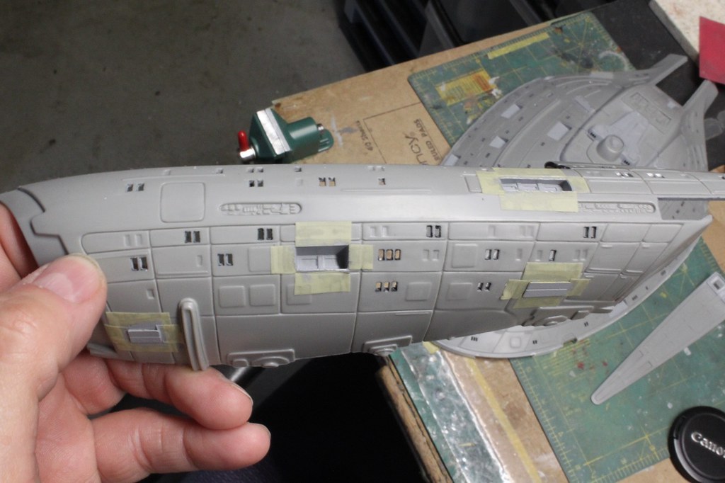
Tube for lower power jack is installed into the secondary hull. I will need to sand and scrape the large seam that runs down the center of the hull.
I’ll also need to remove some plastic for installing more photo-etch:

USS Voyager WIP Img - 093 by Steve J, on Flickr
Mixing up hull color “A” per the Revell instruction sheet. 70% light grey and 30% grey enamel:
USS Voyager WIP Vid - 006 by Steve J, on Flickr
More pics...
Large secondary hull windows are masked off before painting the brass frames with Mister Surfacer thick primer:
USS Voyager WIP Img - 085 by Steve J, on Flickr
Large window groups unmasked after brushing with Mister Surfacer. The curved structural support beams on deck 2 are also given a brush:
USS Voyager WIP Img - 086 by Steve J, on Flickr
Recessed deck 2 egress hatch is painted with Mister Surfacer after modifications were complete:
USS Voyager WIP Img - 087 by Steve J, on Flickr
I found this sheet of .030 clear plastic sheet with its protective film still intact. I will use this to cut individual rectangular bits to fill in the smaller rectagular window openings in the hull. This will take some time to do but it should look great when I’m done:
USS Voyager WIP Img - 088 by Steve J, on Flickr
This is a sheet of extra decals meatloafr over on All Scale Trek printed for me when I was working on the Ent E. He included some sized to fit the Voyager too. Lots of good stuff to help with detailing a variety of kits:
USS Voyager WIP Img - 089 by Steve J, on Flickr
Secondary hull forward photorp launcher openings drilled out and filed to shape.
The openings will be filled with two tiny bits of clear styrene shown to the upper right:
USS Voyager WIP Img - 090 by Steve J, on Flickr
Spine photorp launchers opened up. Kit molded frames were sanded off and will be replaced with the thicker frames made from Evergreen strip shown to the right. Clear rectangular styrene bits will be inserted thru the new frames and out the back for lighting:
USS Voyager WIP Img - 091 by Steve J, on Flickr
The secondary hull is glued together. A strip of white Plasruct is glued into the lower secondary hull to reinforce the seam between the assembled hull halves:
USS Voyager WIP Img - 092 by Steve J, on Flickr
Tube for lower power jack is installed into the secondary hull. I will need to sand and scrape the large seam that runs down the center of the hull.
I’ll also need to remove some plastic for installing more photo-etch:
USS Voyager WIP Img - 093 by Steve J, on Flickr
-
Trekkriffic
- Jack of all Trades
- Posts: 697
- Joined: April 18th, 2014, 10:15 pm
Re: Now … Voyager…
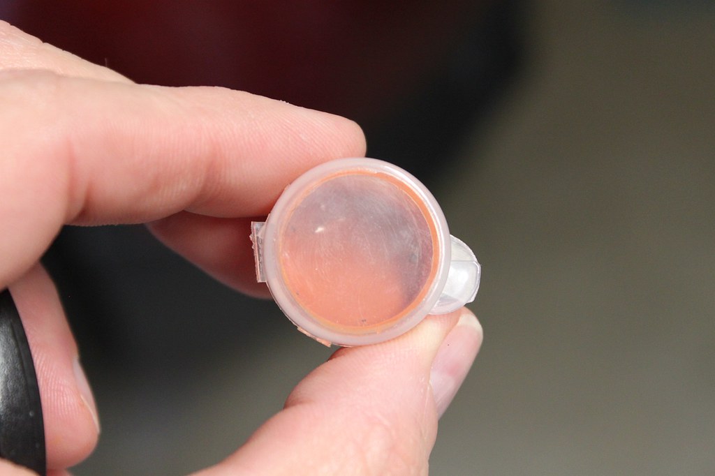
Size K DC coaxial power jack:

USS Voyager WIP Img - 094 by Steve J, on Flickr
Upper saucer brass window frames reinforced with AVES Apoxy Sculpt at the edges to prevent them from popping off if pressed on during the tape masking process when the hull gets its final coats:

USS Voyager WIP Img - 095 by Steve J, on Flickr
Custom display stand components:

USS Voyager WIP Img - 096 by Steve J, on Flickr
The display tube is made up of two sections of brass tubing:

USS Voyager WIP Img - 097 by Steve J, on Flickr
Test fitting display tube to wooden base. The tube sports a size K coaxial power plug mating to the size K jack in the underside of the ship:
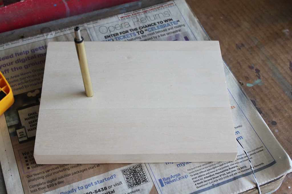
USS Voyager WIP Img - 098 by Steve J, on Flickr
Test fit of taped together model sitting level on the display stand:

USS Voyager WIP Img - 099 by Steve J, on Flickr
Various photo-etch hatches and panels are glued onto the ventral surface of the secondary hull using slow cure CA.
This is some very nice added detail:

USS Voyager WIP Img - 100 by Steve J, on Flickr
I used this green pre-wired SMD LED to illuminate two fiber optic strands for the starboard nacelle upper and lower aft running lights.
A white plastic tube houses the LED and the ends of the strands that butt up against it:
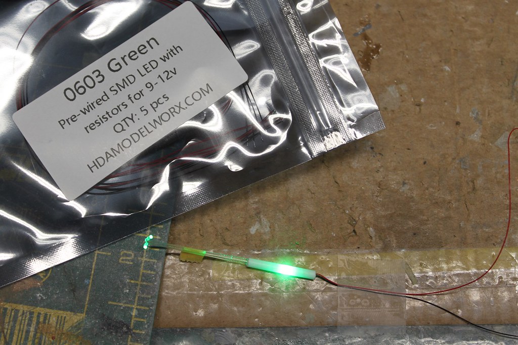
USS Voyager WIP Img - 101 by Steve J, on Flickr
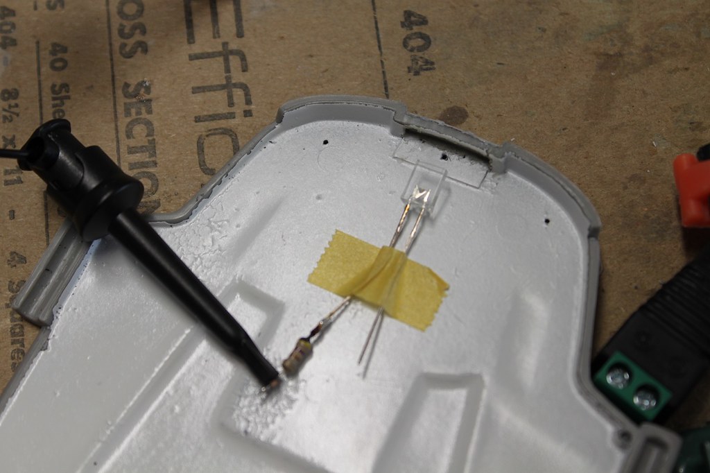
Backside of a section of high density ultra narrow blue LED strip . I had to solder 30 AWG solid Kynar wire to the two grain-of-rice sized contacts on the end of the strip. Each contact is about 1 mm long by 0.5 mm wide. I didn’t have any black Kynar so went with white for the positive and red for the negative leg:

USS Voyager WIP Img - 102 by Steve J, on Flickr
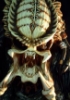
This reminded me of one of those stick insects. The rarely seen, ultra thin, LED strip light insect - Exiguum Spoliare Lumen Insectum:

USS Voyager WIP Img - 103 by Steve J, on Flickr
USS Voyager WIP Img - 094 by Steve J, on Flickr
Upper saucer brass window frames reinforced with AVES Apoxy Sculpt at the edges to prevent them from popping off if pressed on during the tape masking process when the hull gets its final coats:
USS Voyager WIP Img - 095 by Steve J, on Flickr
Custom display stand components:
USS Voyager WIP Img - 096 by Steve J, on Flickr
The display tube is made up of two sections of brass tubing:
USS Voyager WIP Img - 097 by Steve J, on Flickr
Test fitting display tube to wooden base. The tube sports a size K coaxial power plug mating to the size K jack in the underside of the ship:
USS Voyager WIP Img - 098 by Steve J, on Flickr
Test fit of taped together model sitting level on the display stand:
USS Voyager WIP Img - 099 by Steve J, on Flickr
Various photo-etch hatches and panels are glued onto the ventral surface of the secondary hull using slow cure CA.
This is some very nice added detail:
USS Voyager WIP Img - 100 by Steve J, on Flickr
I used this green pre-wired SMD LED to illuminate two fiber optic strands for the starboard nacelle upper and lower aft running lights.
A white plastic tube houses the LED and the ends of the strands that butt up against it:
USS Voyager WIP Img - 101 by Steve J, on Flickr
Backside of a section of high density ultra narrow blue LED strip . I had to solder 30 AWG solid Kynar wire to the two grain-of-rice sized contacts on the end of the strip. Each contact is about 1 mm long by 0.5 mm wide. I didn’t have any black Kynar so went with white for the positive and red for the negative leg:
USS Voyager WIP Img - 102 by Steve J, on Flickr
This reminded me of one of those stick insects. The rarely seen, ultra thin, LED strip light insect - Exiguum Spoliare Lumen Insectum:
USS Voyager WIP Img - 103 by Steve J, on Flickr
-
Trekkriffic
- Jack of all Trades
- Posts: 697
- Joined: April 18th, 2014, 10:15 pm
Re: Now … Voyager…
The LED strip will be attached to the vertical face of a section of right angle plastic channel installed atop a section of 3 mm square tubing glued along the centerline of the lower nacelle half. A strip of adhesive backed aluminum foil can be seen stuck down to the horizontal face of the channel below where the LED strip will be located:

USS Voyager WIP Img - 104 by Steve J, on Flickr
Light test of green starboard nacelle formation light:

USS Voyager WIP Img - 105 by Steve J, on Flickr
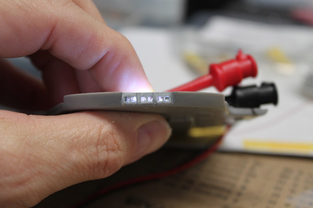
Blue LED strip light test after gluing into nacelle:

USS Voyager WIP Img - 106 by Steve J, on Flickr
Light test using LED strip without diffusion:

USS Voyager WIP Img - 107 by Steve J, on Flickr
I used thin styrofoam packing sheet folded over on itself six layers thick to eliminate any hot spots:

USS Voyager WIP Img - 108 by Steve J, on Flickr
Port nacelle red formation light tested:

USS Voyager WIP Img - 110 by Steve J, on Flickr
I used a tiny pre-wired SMD LED (about the size of a flea) inside a piece of styrene tubing into which a short length of fiber optic strand was inserted. The strand takes a 90 degree turn before exiting the hull thru a small hole I had drilled previously. I bent the fiber over the tip of my soldering iron before it got too hot:

USS Voyager WIP Img - 111 by Steve J, on Flickr
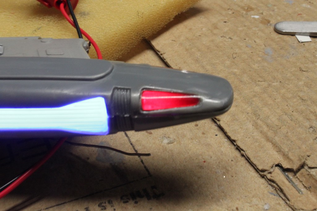
Port nacelle lower red formation light. Lit by a fiber optic strand:

USS Voyager WIP Img - 112 by Steve J, on Flickr
Clear bussard inserts are glued in place after some modification. AVES Apoxy Sculpt was used to fill in any small gaps:

USS Voyager WIP Img - 113 by Steve J, on Flickr
Upper nacelle half after installation of the clear bussard parts. The inside surface was sanded with 600 grit paper to help diffuse the red light from the LEDs which will be installed in the lower half:

USS Voyager WIP Img - 114 by Steve J, on Flickr
That's all for now. Please forgive the massive photo blast; as you can see, I had some catching up to do with my posts.
USS Voyager WIP Img - 104 by Steve J, on Flickr
Light test of green starboard nacelle formation light:
USS Voyager WIP Img - 105 by Steve J, on Flickr
Blue LED strip light test after gluing into nacelle:
USS Voyager WIP Img - 106 by Steve J, on Flickr
Light test using LED strip without diffusion:
USS Voyager WIP Img - 107 by Steve J, on Flickr
I used thin styrofoam packing sheet folded over on itself six layers thick to eliminate any hot spots:
USS Voyager WIP Img - 108 by Steve J, on Flickr
Port nacelle red formation light tested:
USS Voyager WIP Img - 110 by Steve J, on Flickr
I used a tiny pre-wired SMD LED (about the size of a flea) inside a piece of styrene tubing into which a short length of fiber optic strand was inserted. The strand takes a 90 degree turn before exiting the hull thru a small hole I had drilled previously. I bent the fiber over the tip of my soldering iron before it got too hot:
USS Voyager WIP Img - 111 by Steve J, on Flickr
Port nacelle lower red formation light. Lit by a fiber optic strand:
USS Voyager WIP Img - 112 by Steve J, on Flickr
Clear bussard inserts are glued in place after some modification. AVES Apoxy Sculpt was used to fill in any small gaps:
USS Voyager WIP Img - 113 by Steve J, on Flickr
Upper nacelle half after installation of the clear bussard parts. The inside surface was sanded with 600 grit paper to help diffuse the red light from the LEDs which will be installed in the lower half:
USS Voyager WIP Img - 114 by Steve J, on Flickr
That's all for now. Please forgive the massive photo blast; as you can see, I had some catching up to do with my posts.
-
barad_dur

- Registered Seller

- Bishop of Build Ups
- Posts: 2637
- Joined: June 3rd, 2007, 1:42 am
- Location: King George VA USA
Re: Now … Voyager…
Wow - thanks for all the updates ! Coming along fantastic!
If I understood right, you are going to have to cut that clear sheet to fill each individual window ??!!
If I understood right, you are going to have to cut that clear sheet to fill each individual window ??!!
See my model kit collection on YouTube Model Club TV Episode 86
See my kitbash work-in-progress pics in the Kustomizers section of the clubhouse
Thanks for looking !
See my kitbash work-in-progress pics in the Kustomizers section of the clubhouse
Thanks for looking !
-
Trekkriffic
- Jack of all Trades
- Posts: 697
- Joined: April 18th, 2014, 10:15 pm
-
barad_dur
- Registered Seller
- Bishop of Build Ups
- Posts: 2637
- Joined: June 3rd, 2007, 1:42 am
- Location: King George VA USA
Re: Now … Voyager…
I sincerely admire your patience and tenacity !
See my model kit collection on YouTube Model Club TV Episode 86
See my kitbash work-in-progress pics in the Kustomizers section of the clubhouse
Thanks for looking !
See my kitbash work-in-progress pics in the Kustomizers section of the clubhouse
Thanks for looking !
-
Heavy Metal Spike
- Knight of the Round Bench
- Posts: 13419
- Joined: August 2nd, 2005, 2:07 am
- Location: Vancouver, Canada (ex-pat UK - Birmingham & Scotland!)
Re: Now … Voyager…
Amazing batch of updates - thanks so much for taking the time to do this for us!
Reading your posts is like taking a walk through an old-school hobby shop - so much eye-candy and stuff of interest to learn from.
.
Reading your posts is like taking a walk through an old-school hobby shop - so much eye-candy and stuff of interest to learn from.
.
.
.
. . . . . . . . . . . . . . . . .
.
.
.
. . . . . . . . . . . . . . . . .
.
.
-
tay666

- Site Admin
- Prince of Plastic
- Posts: 17534
- Joined: December 8th, 2003, 11:20 am
- Location: Conneaut Ohio
- Contact:
Re: Now … Voyager…
Trekkriffic wrote: ↑June 14th, 2023, 7:59 pmThat is correct! Each… and every… window…. Aieeeeeeeeeeeh!
Trevor Ylisaari
Check out My Prehistoric Scenes site and forum
"Nothing like a trail of blood
To find your way back home."
WANTED - Bat Rider - produced by Wraiths
Check out My Prehistoric Scenes site and forum
"Nothing like a trail of blood
To find your way back home."
WANTED - Bat Rider - produced by Wraiths
-
bucketfoot-al

- Registered Seller
- Duke of Dry Brush
- Posts: 5391
- Joined: September 10th, 2005, 6:16 am
- Location: The Lone Star State.
- Contact:
Re: Now … Voyager…
The only build I ever did that required that level of detail and complexity was my heavily customized 1/200 scale model battleship Yamato. And that was a pure labor of love. I can't imagine having the patience to do your kinds of builds on a regular basis. Tip of the hat to you sir!Trekkriffic wrote: ↑June 14th, 2023, 7:59 pmThat is correct! Each… and every… window…. Aieeeeeeeeeeeh!

Bucketfoot-Al
http://bucketfoot-al.tripod.com/DinoModels/
"You may all go to Hell. I will go to Texas."
-Davy Crockett
http://bucketfoot-al.tripod.com/DinoModels/
"You may all go to Hell. I will go to Texas."
-Davy Crockett
-
Trekkriffic
- Jack of all Trades
- Posts: 697
- Joined: April 18th, 2014, 10:15 pm
Re: Now … Voyager…
Thanks for the nice comment. Thankfully the windows are square or rectangular. Rounded corners would be a real pain.bucketfoot-al wrote: ↑June 15th, 2023, 9:54 amThe only build I ever did that required that level of detail and complexity was my heavily customized 1/200 scale model battleship Yamato. And that was a pure labor of love. I can't imagine having the patience to do your kinds of builds on a regular basis. Tip of the hat to you sir!Trekkriffic wrote: ↑June 14th, 2023, 7:59 pmThat is correct! Each… and every… window…. Aieeeeeeeeeeeh!
-
Trekkriffic
- Jack of all Trades
- Posts: 697
- Joined: April 18th, 2014, 10:15 pm
Re: Now … Voyager…
Warping right along…
Decided to test out the backlit panel I installed in the top half of the fantail. I'm using a rectangular cool white ultrabright LED:
USS Voyager WIP Img - 116 by Steve J, on Flickr
I glued a rectangular section of .010 thick clear styrene behind the brass window frames in the upper half of the fantail parts. Then I trimmed the margins of the backlit panel to fit behind the clear plastic windows and pressed it snugly into place.
The window frames will be retouched later on with more of the light grey hull color:

USS Voyager WIP Img - 117 by Steve J, on Flickr
Held upside down but shows off the fantail windows with backlit panel lit up. Overexposed a tad in this photo; it looks better in person:
USS Voyager WIP Img - 118 by Steve J, on Flickr
Pursuing the wiring theme…
First nacelle light test with bussard LEDs tied into the blue LED strip circuit:

USS Voyager WIP Img - 118 by Steve J, on Flickr
Forward bussard red LEDs with 470 ohm resistors are soldered in a parallel circuit from wires soldered to contacts on the end of the blue LED strip. Devcon Weld-it household adhesive has insulating properties so I will spread it all over the legs of the LEDs as well as the wires and solder joints once the glue dries I will cover the wiring up with a thin piece of aluminum mylar for better light reflectance:

USS Voyager WIP Img - 119 by Steve J, on Flickr
Light test. Note a diffusion panel made from a folded tube of styrofoam packing sheet between the clear warp grills and the blue LED strip and mylar foil in the nose under the red LED lights:

USS Voyager WIP Img - 120 by Steve J, on Flickr
Wires from the blue LED strip and green formation light LED are paired and soldered together before being soldered to the positive and negative power leads:

USS Voyager WIP Img - 121 by Steve J, on Flickr
A single 2mm amber LED provides illumination to both the forward intake (not shown because it’s on the upper half of the wing) and both upper and lower halves of the rear exhaust vents. Blobs of Devcon Weld-It Adhesive hold the wiring in place and serve to insulate any solder joints due to its insulating properties:

USS Voyager WIP Img - 124 by Steve J, on Flickr
Impulse engine exhaust vents after glue up. A diffuser panel behind the vents filters light from a single 2mm amber LED:

USS Voyager WIP Img - 125 by Steve J, on Flickr
Impulse engine intake vent lit with an amber 2mm LED. A diffuser panel made by sanding a small rectangle of .010 clear styrene sits up against the back of the photo-etch brass screen:

USS Voyager WIP Img - 126 by Steve J, on Flickr
Next up… light tests of the completed starboard nacelle.
Decided to test out the backlit panel I installed in the top half of the fantail. I'm using a rectangular cool white ultrabright LED:
USS Voyager WIP Img - 116 by Steve J, on Flickr
I glued a rectangular section of .010 thick clear styrene behind the brass window frames in the upper half of the fantail parts. Then I trimmed the margins of the backlit panel to fit behind the clear plastic windows and pressed it snugly into place.
The window frames will be retouched later on with more of the light grey hull color:
USS Voyager WIP Img - 117 by Steve J, on Flickr
Held upside down but shows off the fantail windows with backlit panel lit up. Overexposed a tad in this photo; it looks better in person:
USS Voyager WIP Img - 118 by Steve J, on Flickr
Pursuing the wiring theme…
First nacelle light test with bussard LEDs tied into the blue LED strip circuit:
USS Voyager WIP Img - 118 by Steve J, on Flickr
Forward bussard red LEDs with 470 ohm resistors are soldered in a parallel circuit from wires soldered to contacts on the end of the blue LED strip. Devcon Weld-it household adhesive has insulating properties so I will spread it all over the legs of the LEDs as well as the wires and solder joints once the glue dries I will cover the wiring up with a thin piece of aluminum mylar for better light reflectance:
USS Voyager WIP Img - 119 by Steve J, on Flickr
Light test. Note a diffusion panel made from a folded tube of styrofoam packing sheet between the clear warp grills and the blue LED strip and mylar foil in the nose under the red LED lights:
USS Voyager WIP Img - 120 by Steve J, on Flickr
Wires from the blue LED strip and green formation light LED are paired and soldered together before being soldered to the positive and negative power leads:
USS Voyager WIP Img - 121 by Steve J, on Flickr
A single 2mm amber LED provides illumination to both the forward intake (not shown because it’s on the upper half of the wing) and both upper and lower halves of the rear exhaust vents. Blobs of Devcon Weld-It Adhesive hold the wiring in place and serve to insulate any solder joints due to its insulating properties:
USS Voyager WIP Img - 124 by Steve J, on Flickr
Impulse engine exhaust vents after glue up. A diffuser panel behind the vents filters light from a single 2mm amber LED:
USS Voyager WIP Img - 125 by Steve J, on Flickr
Impulse engine intake vent lit with an amber 2mm LED. A diffuser panel made by sanding a small rectangle of .010 clear styrene sits up against the back of the photo-etch brass screen:
USS Voyager WIP Img - 126 by Steve J, on Flickr
Next up… light tests of the completed starboard nacelle.
-
Trekkriffic
- Jack of all Trades
- Posts: 697
- Joined: April 18th, 2014, 10:15 pm
Re: Now … Voyager…
More nacelle light test images...
Nacelle and winglet halves are glued together using Testors red tube glue;

USS Voyager WIP Img - 127 by Steve J, on Flickr
Amber Impulse engine and green starboard formation light aglow. Will need some filler putty and light sanding before primer and finish paint coats:

USS Voyager WIP Img - 128 by Steve J, on Flickr

USS Voyager WIP Img - 129 by Steve J, on Flickr
Lit bussard detail. I used the same material to diffuse the light from the warp grills and the bussards. This looks even better to the naked eye:
USS Voyager WIP Img - 130 by Steve J, on Flickr
That's it for now. I added some additional detail to the aft ends of the nacelles using half round Evergreen rod.
I also added a tiny round piece of tubing to the slot in that U shaped thing atop the impulse engines.
Pictures to follow shortly once I download them to my laptop.
Nacelle and winglet halves are glued together using Testors red tube glue;
USS Voyager WIP Img - 127 by Steve J, on Flickr
Amber Impulse engine and green starboard formation light aglow. Will need some filler putty and light sanding before primer and finish paint coats:
USS Voyager WIP Img - 128 by Steve J, on Flickr
USS Voyager WIP Img - 129 by Steve J, on Flickr
Lit bussard detail. I used the same material to diffuse the light from the warp grills and the bussards. This looks even better to the naked eye:
USS Voyager WIP Img - 130 by Steve J, on Flickr
That's it for now. I added some additional detail to the aft ends of the nacelles using half round Evergreen rod.
I also added a tiny round piece of tubing to the slot in that U shaped thing atop the impulse engines.
Pictures to follow shortly once I download them to my laptop.
-
Trekkriffic
- Jack of all Trades
- Posts: 697
- Joined: April 18th, 2014, 10:15 pm
Re: Now … Voyager…
Today's progress...
Ribbed detailing was added to the aft ends of the nacelles. I used half round Evergreen rod attached with CA glue:

USS Voyager WIP Img - 131 by Steve J, on Flickr
A small slice of round Evergreen rod is glued into the slot of the horseshoe atop each impulse engine.
Afterward I filled it with AVES putty leaving a slight indent on top. A tiny detail to be sure:

USS Voyager WIP Img - 132 by Steve J, on Flickr
Masked off the raised rib detail on the clear part behind the main deflector at the front of the secondary hull using Tamiya tape sliced very thin:

USS Voyager WIP Img - 133 by Steve J, on Flickr
Liquid mask was applied to the center section which is semigloss white according to the instructions.
Then I painted the ribs with a mix of rust brown and orange enamels:

USS Voyager WIP Img - 134 by Steve J, on Flickr
I added some more International Orange to the mix for the second coat of the deflector grill ribs:
USS Voyager WIP Img - 135 by Steve J, on Flickr
Wiring up lower half of the fantail with the red and green formation lights and the clear flashing nav light in the center.
The nav light will be wired to a Tenacontrols flasher board in either the secondary or primary hull, haven't decided that yet.
The formation lights don't flash and will be wired to a separate power circuit:

USS Voyager WIP Img - 136 by Steve J, on Flickr
The upper half of the fantail was wired with a rectangular clear LED and light blocked on the top and sides using mylar foil.
I also glued a tiny rare earth magnet between the legs of the LED:

USS Voyager WIP Img - 137 by Steve J, on Flickr
Nacelle wires were paired together - one positive and one negative pair from each nacelle soldered together.
These were then soldered to a single positive and negative feeder wire for each pair.
Shrink tubing was then shrunk down over the solder joints:

USS Voyager WIP Img - 138 by Steve J, on Flickr
Took a break from wiring and sprayed the secondary hull with grey primer.
I sprayed the photo-etch brass hatches and covers with adhesion promoter though before the grey primer.
The nasty seam down the middle was a bitch to fill and sand but I think it looks pretty good now:

USS Voyager WIP Img - 139 by Steve J, on Flickr
I also sprayed the top of the saucer hull with grey primer:

USS Voyager WIP Img - 140 by Steve J, on Flickr
Next I'll start gluing .010 styrene plastic to the backs of the window frames of the larger window groups before attaching the backlit interior room panels that will be lit from behind, I have a roll of "natural white" LED strip I can use for this so they will light up nicely.
Ribbed detailing was added to the aft ends of the nacelles. I used half round Evergreen rod attached with CA glue:
USS Voyager WIP Img - 131 by Steve J, on Flickr
A small slice of round Evergreen rod is glued into the slot of the horseshoe atop each impulse engine.
Afterward I filled it with AVES putty leaving a slight indent on top. A tiny detail to be sure:
USS Voyager WIP Img - 132 by Steve J, on Flickr
Masked off the raised rib detail on the clear part behind the main deflector at the front of the secondary hull using Tamiya tape sliced very thin:
USS Voyager WIP Img - 133 by Steve J, on Flickr
Liquid mask was applied to the center section which is semigloss white according to the instructions.
Then I painted the ribs with a mix of rust brown and orange enamels:
USS Voyager WIP Img - 134 by Steve J, on Flickr
I added some more International Orange to the mix for the second coat of the deflector grill ribs:
USS Voyager WIP Img - 135 by Steve J, on Flickr
Wiring up lower half of the fantail with the red and green formation lights and the clear flashing nav light in the center.
The nav light will be wired to a Tenacontrols flasher board in either the secondary or primary hull, haven't decided that yet.
The formation lights don't flash and will be wired to a separate power circuit:
USS Voyager WIP Img - 136 by Steve J, on Flickr
The upper half of the fantail was wired with a rectangular clear LED and light blocked on the top and sides using mylar foil.
I also glued a tiny rare earth magnet between the legs of the LED:
USS Voyager WIP Img - 137 by Steve J, on Flickr
Nacelle wires were paired together - one positive and one negative pair from each nacelle soldered together.
These were then soldered to a single positive and negative feeder wire for each pair.
Shrink tubing was then shrunk down over the solder joints:
USS Voyager WIP Img - 138 by Steve J, on Flickr
Took a break from wiring and sprayed the secondary hull with grey primer.
I sprayed the photo-etch brass hatches and covers with adhesion promoter though before the grey primer.
The nasty seam down the middle was a bitch to fill and sand but I think it looks pretty good now:
USS Voyager WIP Img - 139 by Steve J, on Flickr
I also sprayed the top of the saucer hull with grey primer:
USS Voyager WIP Img - 140 by Steve J, on Flickr
Next I'll start gluing .010 styrene plastic to the backs of the window frames of the larger window groups before attaching the backlit interior room panels that will be lit from behind, I have a roll of "natural white" LED strip I can use for this so they will light up nicely.
-
Heavy Metal Spike
- Knight of the Round Bench
- Posts: 13419
- Joined: August 2nd, 2005, 2:07 am
- Location: Vancouver, Canada (ex-pat UK - Birmingham & Scotland!)
Re: Now … Voyager…
Trekkriffic wrote: ↑June 21st, 2023, 12:45 am . . . Masked off the raised rib detail on the clear part behind the main deflector at the front of the secondary hull using Tamiya tape sliced very thin:
No way . . . I mean - REALLY ?!?!?!


.
.
.
. . . . . . . . . . . . . . . . .
.
.
.
. . . . . . . . . . . . . . . . .
.
.
-
barad_dur
- Registered Seller
- Bishop of Build Ups
- Posts: 2637
- Joined: June 3rd, 2007, 1:42 am
- Location: King George VA USA
Re: Now … Voyager…
My thoughts exactly Ian !!!
See my model kit collection on YouTube Model Club TV Episode 86
See my kitbash work-in-progress pics in the Kustomizers section of the clubhouse
Thanks for looking !
See my kitbash work-in-progress pics in the Kustomizers section of the clubhouse
Thanks for looking !
-
tay666
- Site Admin
- Prince of Plastic
- Posts: 17534
- Joined: December 8th, 2003, 11:20 am
- Location: Conneaut Ohio
- Contact:
Re: Now … Voyager…
Yep.Heavy Metal Spike wrote: ↑June 21st, 2023, 12:52 amTrekkriffic wrote: ↑June 21st, 2023, 12:45 am . . . Masked off the raised rib detail on the clear part behind the main deflector at the front of the secondary hull using Tamiya tape sliced very thin:
No way . . . I mean - REALLY ?!?!?!
.
I saw that and just thought "HOW? "
Trevor Ylisaari
Check out My Prehistoric Scenes site and forum
"Nothing like a trail of blood
To find your way back home."
WANTED - Bat Rider - produced by Wraiths
Check out My Prehistoric Scenes site and forum
"Nothing like a trail of blood
To find your way back home."
WANTED - Bat Rider - produced by Wraiths
-
bucketfoot-al
- Registered Seller
- Duke of Dry Brush
- Posts: 5391
- Joined: September 10th, 2005, 6:16 am
- Location: The Lone Star State.
- Contact:
Re: Now … Voyager…
Wait - WHUT???!!!??? 

Bucketfoot-Al
http://bucketfoot-al.tripod.com/DinoModels/
"You may all go to Hell. I will go to Texas."
-Davy Crockett
http://bucketfoot-al.tripod.com/DinoModels/
"You may all go to Hell. I will go to Texas."
-Davy Crockett
-
Trekkriffic
- Jack of all Trades
- Posts: 697
- Joined: April 18th, 2014, 10:15 pm
Re: Now … Voyager…
Thanks guys.
Just got these in the mail from Shapeways…
Voyager Shuttle Bay Interior Replacement

USS Voyager WIP Img - 141 by Steve J, on Flickr
Voyager Shuttlecraft Pack

USS Voyager WIP Img - 142 by Steve J, on Flickr
Both kits are molded in clear ultra fine detail plastic suitable for lighting.
The type 8 and 9 shuttles are hollow with internal cockpit seats and rear walls.
Hard to believe based on the wee size of these tiny ships.
Good thing I have some clear white flea sized SMD LED’s from HDA Modelworx.
Hopefully meatloafr over on AST can help me with decals as Shapeways doesn’t provide any.
Oh yeah… this is gonna be fun!
Just got these in the mail from Shapeways…
Voyager Shuttle Bay Interior Replacement
USS Voyager WIP Img - 141 by Steve J, on Flickr
Voyager Shuttlecraft Pack
USS Voyager WIP Img - 142 by Steve J, on Flickr
Both kits are molded in clear ultra fine detail plastic suitable for lighting.
The type 8 and 9 shuttles are hollow with internal cockpit seats and rear walls.
Hard to believe based on the wee size of these tiny ships.
Good thing I have some clear white flea sized SMD LED’s from HDA Modelworx.
Hopefully meatloafr over on AST can help me with decals as Shapeways doesn’t provide any.
Oh yeah… this is gonna be fun!